Simple circuits for radio amateurs to repeat. Electronic homemade products for radio amateurs and novice electricians. Designation of power supplies
Recently, having learned that I am a radio amateur, two people turned to me for help on the forum of our city, in the Radio branch. Both for different reasons, and both of different ages, already adults, as it turned out during the meeting, one was 45 years old, the other 27. Which proves that you can start studying electronics at any age. They were united by one thing, both were somehow familiar with technology, and would like to master the radio business on their own, but did not know where to start. We continued our conversation in In contact with, to my answer that there is a sea of \u200b\u200binformation on this topic on the Internet, do it - I don’t want to, I heard from both about the same - that both do not know where to start. One of the first questions was: what is included in the required minimum knowledge of a radio amateur. It took quite a long time to list the necessary skills for them, and I decided to write a review on this topic. I think it will be useful for beginners like my friends, for everyone who cannot decide where to start their training.
I must say right away that when learning, you need to evenly combine theory with practice. No matter how much you want to quickly start soldering and assembling specific devices, you need to remember that without the necessary theoretical base in your head, at best, you can accurately copy other people's devices. Whereas if you know the theory, at least in a minimal amount, you can change the scheme and fit it to your needs. There is such a phrase, I think known to every radio amateur: "There is nothing more practical than a good theory."

First of all, you need to learn how to read circuit diagrams. Without the ability to read circuits, it is impossible to assemble even the simplest electronic device. Also, subsequently, it will not be superfluous to master the independent drawing up of circuit diagrams, in a special one.

Soldering parts
It is necessary to be able to identify by appearance, any radio component, and know how it is indicated on the diagram. Of course, in order to assemble, solder any circuit, you need to have a soldering iron, preferably not higher than 25 watts, and be able to use it well. All semiconductor parts do not like overheating, if you are soldering, for example, a transistor to a board, and you could not solder the output in 5 - 7 seconds, interrupt for 10 seconds, or solder another part at this time, otherwise there is a high probability of burning the radio component from overheating.

It is also important to solder carefully, especially closely located leads of radio components, and not to hang “snot”, accidental short circuits. Always, if in doubt, ring a suspicious place with a multimeter in sound dialing mode.

It is equally important to remove flux residue from the board, especially if you are soldering digital circuits, or with flux containing active additives. Rinse off with a special liquid, or 97% ethyl alcohol.

Beginners often assemble circuits by surface mounting, right on the pins of the parts. I agree that if the conclusions are securely twisted together, and then soldered, such a device will last a long time. But in this way it is no longer worth assembling devices containing more than 5 - 8 parts. In this case, you need to assemble the device on a printed circuit board. The device assembled on the board is highly reliable, the connection diagram can be easily traced along the tracks, and, if necessary, all connections can be called with a multimeter.

The downside of printed wiring is the difficulty of changing the scheme of the finished device. Therefore, before wiring and etching the PCB, you always first need to assemble the device on a breadboard. You can make devices on printed circuit boards in different ways, the main thing here is to observe one important rule: copper foil tracks on textolite should not have contact with other tracks, where this is not provided for by the scheme.

In general, there are different ways to make a printed circuit board, for example, by separating sections of the foil - tracks, a groove cut through a cutter in the foil made from a hacksaw blade. Or by applying a protective pattern that protects the foil under it, (future tracks) from etching with a permanent marker.

Or with the help of LUT technology (laser - ironing technology), where the tracks are protected from etching by the burnt toner. In any case, no matter how we make a printed circuit board, we need to first route it in the tracer program. I recommend for beginners, this is a manual tracer with great features.

Also, when wiring printed circuit boards yourself, or if you printed a finished board, you need the ability to work with the documentation for the radio component, with the so-called Datasheets ( Datasheet), pages in PDF format. There are datasheets on the Internet for almost all imported radio components, with the exception of some Chinese ones.

On domestic radio components, you can find information in scanned directories, specialized sites that host pages with the characteristics of radio components, and information pages of various online stores such as Chip & Dip. It is necessary to be able to determine the pinout of the radio component, the name pinout is also found, because very many, even two-output parts have polarity. It also requires practical skills in working with a multimeter.

A multimeter is a universal device, with the help of only one of it, you can carry out diagnostics, determine the conclusions of the part, their performance, the presence or absence of a short circuit on the board. I think it’s not superfluous to remind, especially to young novice radio amateurs, the observance of electrical safety measures when debugging the operation of the device.

After assembling the device, you need to arrange it in a beautiful case so that you are not ashamed to show it to your friends, which means that you need locksmith skills if the case is made of metal or plastic, or carpentry if the case is made of wood. Sooner or later, any radio amateur comes to the conclusion that he has to deal with minor repairs of equipment, first his own, and then with the acquisition of experience, and from friends. And this means that it is necessary to be able to diagnose a malfunction, determine the cause of the breakdown, and then eliminate it.

Often even experienced radio amateurs, without tools, find it difficult to desolder multi-pin parts from the board. It’s good if the parts are being replaced, then we bite off the leads near the case itself, and solder the legs one at a time. It is worse and more difficult when this part is needed to assemble some other device, or a repair is being made, and the part may need to be soldered back after, for example, when looking for a short circuit on the board. In this case, tools for dismantling are needed, and the ability to use them is a braid and a desoldering pump.

I don’t mention the use of a soldering iron, due to the frequent lack of access for beginners to it.
Conclusion
All of the above is only part of the necessary minimum that a novice radio amateur should know when designing devices, but with these skills, you can already assemble, with a little experience, almost any device. Specially for the site AKV.
Discuss the article HOW TO START FOR A RADIO AMATEUR
Below are simple light and sound circuits, mainly assembled on the basis of multivibrators, for beginner radio amateurs. In all circuits, the simplest element base is used, complex adjustment is not required, and elements can be replaced with similar ones within a wide range.
Electronic duck
A toy duck can be equipped with a simple two-transistor "quack" simulator circuit. The circuit is a classic two-transistor multivibrator with an acoustic capsule in one arm, and two LEDs that can be inserted into the eyes of the toy serve as the load of the other. Both of these loads work alternately - either a sound is heard, or LEDs flash - the eyes of a duck. A reed switch can be used as a power switch SA1 (can be taken from the SMK-1, SMK-3, etc. sensors used in security alarm systems as door opening sensors). When a magnet is brought to the reed switch, its contacts are closed and the circuit starts to work. This can happen when the toy is tilted to a hidden magnet or a kind of “magic wand” with a magnet is brought up.
Transistors in the circuit can be any p-n-p type, low or medium power, for example MP39 - MP42 (old type), KT 209, KT502, KT814, with a gain of more than 50. You can also use transistors of the n-p-n structure, for example KT315, KT 342, KT503 , but then you need to change the polarity of the power supply, turn on the LEDs and the polar capacitor C1. As an acoustic emitter BF1, you can use a capsule type TM-2 or a small-sized speaker. Establishing the circuit is reduced to the selection of the resistor R1 to obtain a characteristic quacking sound.
The sound of a bouncing metal ball
The circuit quite accurately imitates such a sound, as the capacitor C1 discharges, the volume of the “beats” decreases, and the pauses between them decrease. At the end, a characteristic metallic rattle will be heard, after which the sound will stop.

Transistors can be replaced with similar ones, as in the previous circuit.
The total duration of the sound depends on the capacitance C1, and C2 determines the duration of the pauses between the “beats”. Sometimes, for a more believable sound, it is useful to choose a transistor VT1, since the operation of the simulator depends on its initial collector current and gain (h21e).
Engine Sound Simulator
They can, for example, sound a radio-controlled or other model of a mobile device.

Transistor and speaker replacement options - as in the previous circuits. Transformer T1 is the output from any small-sized radio receiver (a speaker is also connected through it in the receivers).
There are many schemes for imitating the sounds of birdsong, animal voices, the whistle of a locomotive, etc. The circuit proposed below is assembled on just one digital microcircuit K176LA7 (K561 LA7, 564LA7) and allows you to simulate many different sounds depending on the resistance value connected to the X1 input contacts.

It should be noted that the microcircuit here works “without power”, that is, no voltage is applied to its positive output (leg 14). Although, in fact, the microcircuit is still powered, but this happens only when the resistance-sensor is connected to the X1 contacts. Each of the eight inputs of the microcircuit is connected to the internal power bus through diodes that protect against static electricity or incorrect connection. Through these internal diodes, the microcircuit is powered due to the presence of positive feedback on power supply through the input resistor-sensor.
The circuit consists of two multivibrators. The first one (on the elements DD1.1, DD1.2) immediately starts generating rectangular pulses with a frequency of 1 ... 3 Hz, and the second one (DD1.3, DD1.4) starts working when the logic level " 1". It generates tone pulses with a frequency of 200 ... 2000 Hz. From the output of the second multivibrator, pulses are fed to a power amplifier (transistor VT1) and a modulated sound is heard from the dynamic head.
If you now connect a variable resistor with a resistance of up to 100 kOhm to the input jacks X1, then there is a feedback on the power supply and this transforms the monotonous intermittent sound. By moving the slider of this resistor and changing the resistance, you can achieve a sound reminiscent of the trill of a nightingale, the chirping of a sparrow, the quacking of a duck, the croaking of a frog, etc.
Details
The transistor can be replaced with KT3107L, KT361G, but in this case, you need to put R4 with a resistance of 3.3 kOhm, otherwise the sound volume will decrease. Capacitors and resistors - of any type with ratings close to those indicated on the diagram. It must be borne in mind that the above-mentioned protective diodes are absent in the K176 series microcircuits of early releases and such instances will not work in this circuit! It is easy to check the presence of internal diodes - just measure the resistance between pin 14 of the microcircuit (“+” power supply) and its input terminals (or at least one of the inputs) with a tester. As with testing diodes, resistance should be low in one direction and high in the other.
The power switch in this circuit can be omitted, since in rest mode the device consumes less than 1 μA current, which is much less than even the self-discharge current of any battery!
Adjustment
A correctly assembled simulator does not require any adjustment. To change the tone of the sound, you can select a capacitor C2 from 300 to 3000 pF and resistors R2, R3 from 50 to 470 kOhm.
flasher
The flashing frequency of the lamp can be adjusted by selecting the elements R1, R2, C1. The lamp can be from a flashlight or a car 12 V. Depending on this, you need to choose the supply voltage of the circuit (from 6 to 12 V) and the power of the switching transistor VT3.
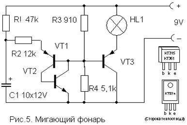
Transistors VT1, VT2 - any low-power corresponding structures (KT312, KT315, KT342, KT 503 (n-p-n) and KT361, KT645, KT502 (p-n-p), and VT3 - medium or high power (KT814, KT816, KT818).
A simple device for listening to the sound of TV programs on headphones. It does not require any power and allows you to move freely within the room.

Coil L1 is a "loop" of 5 ... 6 turns of wire PEV (PEL) -0.3 ... 0.5 mm, laid along the perimeter of the room. It is connected in parallel with the TV speaker through the SA1 switch as shown in the figure. For normal operation of the device, the output power of the TV sound channel must be within 2 ... 4 W, and the loop resistance must be 4 ... 8 Ohms. The wire can be laid under the plinth or in the cable duct, while it must be placed as far as possible no closer than 50 cm from the wires of the 220 V network to reduce AC voltage interference.

Coil L2 is wound on a frame made of thick cardboard or plastic in the form of a ring with a diameter of 15 ... 18 cm, which serves as a headband. It contains 500 ... 800 turns of PEV (PEL) wire 0.1 ... 0.15 mm fixed with glue or electrical tape. A miniature volume control R and an earphone (high-resistance, for example, TON-2) are connected in series to the coil terminals.
Automatic light switch
This one differs from many schemes of similar automata by its extreme simplicity and reliability and does not need a detailed description. It allows you to turn on the lighting or some electrical appliance for a specified short time, and then automatically turns it off.

To turn on the load, it is enough to briefly press the switch SA1 without fixing. In this case, the capacitor has time to charge and opens the transistor, which controls the switching on of the relay. The turn-on time is determined by the capacitance of the capacitor C and with the nominal value indicated on the diagram (4700 mF) is about 4 minutes. An increase in the on-time is achieved by connecting additional capacitors in parallel with C.
The transistor can be any n-p-n type of medium power or even low power, such as KT315. It depends on the operating current of the relay used, which can also be any other for an actuation voltage of 6-12 V and capable of switching the load of the power you need. You can also use p-n-p type transistors, but you will need to change the polarity of the supply voltage and turn on the capacitor C. Resistor R also affects the response time to a small extent and can be 15 ... 47 kOhm, depending on the type of transistor.
List of radio elements
| Designation | Type | Denomination | Quantity | Note | Shop | My notepad | |
|---|---|---|---|---|---|---|---|
| Electronic duck | |||||||
| VT1, VT2 | bipolar transistor | KT361B | 2 | MP39-MP42, KT209, KT502, KT814 | To notepad | ||
| HL1, HL2 | Light-emitting diode | AL307B | 2 | To notepad | |||
| C1 | 100uF 10V | 1 | To notepad | ||||
| C2 | Capacitor | 0.1uF | 1 | To notepad | |||
| R1, R2 | Resistor | 100 kOhm | 2 | To notepad | |||
| R3 | Resistor | 620 ohm | 1 | To notepad | |||
| BF1 | Acoustic emitter | TM2 | 1 | To notepad | |||
| SA1 | reed switch | 1 | To notepad | ||||
| GB1 | Battery | 4.5-9V | 1 | To notepad | |||
| Bouncing metal ball sound simulator | |||||||
| bipolar transistor | KT361B | 1 | To notepad | ||||
| bipolar transistor | KT315B | 1 | To notepad | ||||
| C1 | electrolytic capacitor | 100uF 12V | 1 | To notepad | |||
| C2 | Capacitor | 0.22uF | 1 | To notepad | |||
| dynamic head | GD 0.5...1Watt 8 Ohm | 1 | To notepad | ||||
| GB1 | Battery | 9 Volt | 1 | To notepad | |||
| Engine Sound Simulator | |||||||
| bipolar transistor | KT315B | 1 | To notepad | ||||
| bipolar transistor | KT361B | 1 | To notepad | ||||
| C1 | electrolytic capacitor | 15uF 6V | 1 | To notepad | |||
| R1 | Variable resistor | 470 kOhm | 1 | To notepad | |||
| R2 | Resistor | 24 kOhm | 1 | To notepad | |||
| T1 | Transformer | 1 | From any small radio receiver | To notepad | |||
| Universal sound simulator | |||||||
| DD1 | Chip | K176LA7 | 1 | K561LA7, 564LA7 | To notepad | ||
| bipolar transistor | KT3107K | 1 | KT3107L, KT361G | To notepad | |||
| C1 | Capacitor | 1 uF | 1 | To notepad | |||
| C2 | Capacitor | 1000 pF | 1 | To notepad | |||
| R1-R3 | Resistor | 330 kOhm | 1 | To notepad | |||
| R4 | Resistor | 10 kOhm | 1 | To notepad | |||
| dynamic head | GD 0.1...0.5Watt 8 Ohm | 1 | To notepad | ||||
| GB1 | Battery | 4.5-9V | 1 | To notepad | |||
| flasher | |||||||
| VT1, VT2 | bipolar transistor | ||||||
amateur radio technology. The book tells about the technology of the radio amateur. Recommendations are given for processing materials, winding coils and transformers, assembling and soldering parts. It describes the manufacture of home-made parts of structural elements, the simplest machines, fixtures and tools.

Digital electronics for beginners. The basics of digital electronics are presented in a simple and accessible way for beginners - by creating fun and educational devices on transistors and microcircuits on a breadboard, which immediately start working after assembly, without requiring soldering, adjustment and programming. The set of necessary parts is minimized both in terms of the number of items and in terms of cost.
In the course of the presentation, questions are given for self-examination and consolidation of the material, as well as creative tasks for the independent development of schemes.

Oscilloscopes. Basic principles of measurements. Oscilloscopes are an indispensable tool for those who design, manufacture or repair electronic equipment. In today's fast-paced world, professionals need the best equipment to quickly and accurately solve their daily measurement tasks. As engineers' "eyes" into the world of electronics, oscilloscopes are a key tool for studying the inner workings of electronic circuits.
![]()
Designing and building a Tesla coil is pretty easy. For a beginner this seems like a daunting task (I also found it difficult), but you can get a working coil by following the instructions in this article and doing a little calculation. Of course, if you want a very powerful coil, there is no way other than learning the theory and doing a lot of calculations.

Homemade young radio amateur. The book describes sound simulators, hidden wiring finders, acoustic switches, automatic sound control models, electric musical instruments, electric guitar attachments, color music consoles and other structures assembled from available parts.

School radio station ShK-2 - Alekseev S.M. The brochure describes two transmitters and two receivers operating on the 28 and 144 MHz bands, an anode-screen modulator, a power supply and simple antennas. It also tells about the organization of the work of students at a collective radio station, about the training of operators, the content of their work, about the research work of schoolchildren in the field of distribution of HF and VHF.

Electronics For Dummies
Build your electronics workbench - and begin creating fun electronics projects right away
Packed with hundreds of colorful diagrams and photographs, this book provides step-by-step instructions for experiments that show you how electronic components work, advice on choosing and using essential tools, and exciting projects you can build in 30 minutes or less. You "ll get charged up as you transform theory into action in chapter after chapter!

The book consists of descriptions of simple designs containing electronic components and experiments with them. In addition to traditional designs, whose operation logic is determined by their circuitry, descriptions of products that are functionally implemented using programming have been added. Subjects of products - electronic toys and souvenirs.

How to master radio electronics from scratch. If you have a great desire to be friends with electronics, if you want to create your own homemade products, but don't know where to start, use this tutorial. You will learn how to read circuit diagrams, how to work with a soldering iron, and create a lot of interesting crafts. You will learn how to use a measuring instrument, design and build printed circuit boards, learn the secrets of many professional radio amateurs. In general, get enough knowledge to further master electronics on your own.

Soldering is easy - a step by step guide for beginners. The comic, despite its format and volume, explains in small details the basic principles of this process, which are not at all obvious to people who have never held a soldering iron in their hands (as practice shows, for many who held it too). If you have long wanted to learn how to solder yourself, or plan to teach your children this, then this comic is for you.

Electronics for the curious. This book is written specifically for you, who are starting an exciting ascent to the heights of electronics. Helps to master the dialogue of the author of the book with the beginner. Measuring instruments, breadboard, books and PCs also become assistants in mastering knowledge.

Encyclopedia of a young radio amateur. Here you will find many practical diagrams of both individual nodes and blocks, and entire devices. In resolving many issues, a special guide will help. Using a convenient search system, you will find the desired section, and superbly executed drawings as illustrative examples.

The book was created specifically for beginner radio amateurs, or, as we like to say, "dummies". She talks about the basics of electronics and electrical engineering necessary for a radio amateur. Theoretical questions are told in a very accessible form and in the volume necessary for practical work. The book teaches how to properly solder, measure, analyze circuits. But, rather, this is a book about entertaining electronics. After all, the basis of the book is amateur radio homemade products that are accessible to a beginner radio amateur and useful in everyday life.

This is the second book in a series of publications addressed to the novice radio amateur as an educational and practical aid. In this book, on a more serious level, the acquaintance with various circuits based on a semiconductor and radio-vacuum base, the basics of sound engineering, electrical and radio measurements is continued. The presentation is accompanied by a large number of illustrations and practical diagrams.

Radio amateur's alphabet. The main and only purpose of this book is to introduce children who do not have the slightest idea about it to amateur radio creativity. The book is built on the principle of `from the basics - through acquaintance - to understanding` and can be recommended to middle and high school students as a guide to the beginnings of radio engineering.
You can make the simplest electronic circuits for everyday use with your own hands, even without deep knowledge in electronics. In fact, at the household level, radio is very simple. Knowledge of the elementary laws of electrical engineering (Ohm, Kirchhoff), general principles of operation of semiconductor devices, skills in reading circuits, the ability to work with an electric soldering iron is enough to assemble a simple circuit.
Ham radio workshop
No matter how complex the scheme would have to be, you must have a minimum set of materials and tools in your home workshop:
- Side cutters;
- Tweezers;
- Solder;
- Flux;
- Circuit boards;
- Tester or multimeter;
- Materials and tools for the manufacture of the body of the device.
You should not purchase expensive professional tools and devices to begin with. An expensive soldering station or digital oscilloscope is of little help to a beginner radio amateur. At the beginning of the creative path, the simplest instruments are quite enough, on which you need to hone your experience and skills.

Where to start
Do-it-yourself radio circuits for the home should not exceed the level of complexity that you own, otherwise it will only mean wasted time and materials. With a lack of experience, it is better to limit yourself to the simplest schemes, and as you accumulate skills, improve them, replacing them with more complex ones.
Usually, most of the literature from the field of electronics for beginner radio amateurs gives a classic example of making simple receivers. This is especially true of classical old literature, in which there are not so many fundamental errors in comparison with contemporary literature.
Note! These schemes were designed for the huge power of transmitting radio stations in the past. Today, transmitting centers use less power to transmit and try to get into the shorter wavelength range. Do not waste time trying to make a working radio using the simplest circuit.
Radio circuits for beginners should include a maximum of a couple of active elements - transistors. So it will be easier to understand the operation of the circuit and increase the level of knowledge.
What can be done
What can be done so that it is not difficult and can be used in practice at home? There can be many options:
- apartment call;
- Christmas tree garlands switch;
- Backlight for modding the computer system unit.

Important! Appliances to be powered by household AC power should not be designed unless there is sufficient experience. It is dangerous for life and for others.
Pretty simple circuits have amplifiers for computer speakers, made on specialized integrated circuits. Devices assembled on their basis contain a minimum number of elements and practically do not require adjustment.
You can often find circuits that need elementary alterations, improvements that make it easier to manufacture and configure. But this should be done by an experienced master in order to make the final version more accessible to a beginner.
On what to build
Most of the literature recommends designing simple circuits on circuit boards. At present, this is quite easy. There is a wide variety of circuit boards with different hole patterns and printed tracks.
The principle of installation is that the parts are installed on the board in free places, and then the necessary conclusions are connected to each other by jumpers, as indicated in the circuit diagram.

With due care, such a board can serve as the basis for many circuits. The power of the soldering iron for soldering should not exceed 25 W, then the risk of overheating the radio elements and printed conductors will be minimized.
The solder should be fusible, such as POS-60, and it is best to use pure pine rosin or its solution in ethyl alcohol as a flux.
Highly qualified radio amateurs can design a printed circuit board pattern themselves and execute it on foil material, on which radio elements are then soldered. The design developed in this way will have optimal dimensions.
Design of the finished structure
Looking at the creations of beginners and experienced craftsmen, one can come to the conclusion that the assembly and adjustment of the device is not always the most difficult part of the design process. Sometimes a properly working device remains a set of parts with soldered wires, not closed by any case. At present, you can no longer be puzzled by the manufacture of the case, because on sale you can find all kinds of sets of cases of any configuration and dimensions.

Before you start manufacturing the design you like, you should fully think through all the stages of the work: from the availability of tools and all radio elements to the version of the case. It will be completely uninteresting if in the process of work it turns out that one of the resistors is missing, and there are no replacement options. The work is best done under the guidance of an experienced radio amateur, and, in extreme cases, periodically monitor the manufacturing process at each stage.
Video
Our website contains materials that you will find not only interesting, but also very useful. This section is devoted to "Practical schemes of various devices", it has a lot of reference materials, information for beginner radio amateurs and not only, professionals will also find something useful for themselves. After all, people who want to develop learn throughout their lives. They say that it is impossible to know everything, and we confirm this hypothesis, laying out more and more new materials that illuminate science, electronics and provide constantly new knowledge.
We offer cooperation to experienced radio amateurs, they can share their experience on the pages of our website with beginners, that is, still quite amateurs. Our site will be useful in that participants can write comments on articles, discuss their problems on the forum, thereby sharing their experience with each other.
In case you want to develop, but you just have little experience, our site will be of great benefit to you, the presentation of information is not at the most difficult level, but in order to understand the electrical circuits of various devices, to get acquainted with the description of the principles of their operation, you need to work a little. Therefore, if you are lazy and restless, do not want to work to achieve something, then pass by, our site is not for you. There is no “I want to know everything” button on our site.
Our primary and primary goal is to meet the expectations of our users. We want you to expand your technical knowledge or strengthen what you already have. You will definitely need them, because for many hobbies - amateur radio often develops into a form of active income.
Article updated: 03/25/2019In this article, we will look at a differential pressure gauge, what it is, what its function is, and what it is used for. A differential pressure gauge is a device that measures the difference in pressure between two places. Differential pressure gauges can range from devices simple enough to build at home to sophisticated digital equipment. Function Standard pressure gauges are used to measure the pressure in a container by comparing it…
Article updated: 18.02.2019 Article updated: 02/17/2019 Article updated: 02/14/2019 Article updated: 10.02.2019 Article updated: 01/31/2019 Article updated: 01/30/2019 Article updated: 11/13/2018Post navigation
- Practical schemes of different devices


